Modding
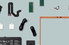
I have just added this paragraph telling you that since I started writing this article my case has changed quite a bit, here are pictures of the case when I first started the article; compare them to some that you see throughout the rest of it.
 |
 |
 |
 |
Recently it seems that everyone thinks that their computer has to be "cool" i mean that in both senses of the word. If your computer has less then about 4 fans inside, you are probably considered a low-end user! now that just doesn't sound right does it? So what do people do to make their computers cool? Well for the first sense of the word, there are all sorts of devices available to reduce the temperature inside of your computer, ranging from the everyday fan to Peltiers and water-cooling systems!
I hope to go through many different methods of cooling and demonstrate as many as possible (not always with my own machine :)
About the second meaning of the word cool, well a computer with no toys would be like boring, wouldn't it? Well it seems that way, devices which we are all thinking about now almost just to make our computers customisable, and good looking include; bay bus& for instance the Creative LiveDrive!
I'm going to start by going through some of the mod& small, but all worthwhile, that I have used on my PC. Here are some pictures of the basic case, looking pretty normal don't you think?
This is my Global Win 802 Case, it has a nice 300W PSU inside, 3 5.25" drive bays, and 2 external 3.25" bays. It may look pretty normal from the outside, but wait till we take a peek under the cover. Anyway, i presume you noticed the removable HDD rack at the top there above the cdrom. That used to come in handy before i set-up my network, but now it is basically redundant, but i use it to control all of my HD activity LED's as i could not seem to get them connected to the mobo directly, also lies a small, but incredibly effective 50mm fan (nicked off an old Pentium 133) taking the HD temperature from around 40°C down to 20°C.
 |
 |
A lot of hard work has gone into making it look this neat and tidy inside (bar the odd bit of masking tape & the "hidden compartment"). Although you may think that copper pipe is a dumb idea as it conducts, but I made sure I only used it where i know it is safe, and no-where near my mobo. You may have noticed that there seems to be an extreme lack of wires inside (I hope so) but in fact, they are all there, I have just tried to as many of the power cables as possible through the front of my case (behind the panelling) and back into the case where they are needed.

I got the cables to look neat as they do by just putting a small line of "UHU" glue on the cable, and holding the cable in position for a few moments. Hopefully i will be either making, or buying a baybus when i get a new Case with more 5.25" bays, I also intend to get the Creative Labs Sound Blaster Live Platinum kit which comes with the LiveDrive, although I have seen something better, which had a VU meter on as well, which looked a lot more "snazzy" called a NewQ Gold available from Outpost.com which i am also considering.


When I first bought this case, it was equipped with just the fan in the PSU and the two on the Athlon chip (550Mhz Overclocked to 750Mhz) although this was quite sufficient, I decided that 50°C was too hot, and so installed an extra fan at the back which draws around 15°C out, leaving the case temperature at about 35°C. As you may not be aware that big black block in the case below the 3.5" bays is empty, it is merely there to hold a fan, but there isn't 1 in place, so it has no real use. I will be ordering another 80mm (as Is already in position on at the back of the case)

The "Hidden Compartment"
Although this doesn't look much, the compartment holds a lot of excess wire, which would normally just hang, and make the computer look untidy, instead it is just slotted underneath the PSU, and a few pieces of well placed masking tape form a lets say "shelf" for wire to be hidden. Also lies a piece of chocolate block on top of the HD which splits the usual Molex 3 ways. Those being; to the FDD, the HD and the HD fan.
 |
 |
 |
 |

Yes you guessed it, nicked from my Pentium 133 again :) Anyway, i had to start somewhere, and i thought that this was easily replaceable if anything went wrong, and in theory it shouldn't take much to give a makeover, this is where i was quite wrong, in terms of paint; it took far more then expected, but i will explain why shortly.
What you will need:
I think this should about cover it,
+Screwdrivers....
+Fine sand paper (the piece i used was meant for wood, but worked a treat)
+Whatever
colour spray paint you require (preferably quick drying. I used
"Odds 'n' Ends" from Wilkinson& +A
lot of space (even my back garden got decorated doing this little job
:) I
started by taking the keyboard to bits, as it is an old one i had to
remove a few screws to get the bottom off, then a few to remove the
circuit board from the base, and then i had to remove every single key
by force. Now I had it in pieces i took a bit of fairly fine sand paper
and took a fine layer off of the keyboard to allow the spray paint to
be applied a little easier. Now it was time to apply the paint to the
keyboard cover... i like warm colours best, so i decided to go for a
red into yellow gradient; easily achieved by spraying from one corner
to the other with one colour, and then the same with the other colour
(just ease it off a bit as you get closer) I
WOULD DEFINITELY ADVISE THAT YOU *DON'T* DO THIS INDOORS (or even in
a garage for that matter as the fumes can be nasty) I
then hung the cable on the washing line, and took a can of blue spray
paint to it, covering it (unfortunately i had little success with this,
the paint did not seem to set properly, and is scratches off too easily,
so i am probably going to have to invest in some lacquer or such like) Next
job is to do the keys... these too I sprayed blue as it goes well against
the red/yellow. This was harder then I expected as the spray comes out
fairly fast, and has a tendency to try and move the key, so i had to
.... Tips
when Modifying your case I
haven't as yet actually made any major changes to my case, as I decided
that I would wait until I get a new one, but i'm going to explain how
you should go about it. First
of all a few suggestions; +Try
to decide what you are going to do before you start doing it. +When
using any electrical for cutting and such like always use it on a bare
case, make sure there is nothing inside it, as metal splinters on your
motherboard or such like will almost certainly short it. +When
cutting holes in the case to fit fans and such like make the hole a
little smaller then it needs to be, as you can always make it larger,
whereas you cannot make it smaller! +Cut
firstly with a more powerful piece of equipment, and then use a finer,
more gentle one to finish the job, leaving more smooth, and safe edges. +To
make the job look more professional, and neat line your holes with a
small rubber trim. +Use
masking tape on the surface, which you are cutting to prevent it being
scratched. +When
planning to where to place a window take into consideration that you
may want certain features to be hidden, and therefore leave space around
the window where you can run cables e.t.c which you don't want to be
seen through the window. +If
the material you use for your window (usually Plexiglas) comes with
a protective layer on, then I suggest you do not remove it until you
are completely done. +Do
not do up screws too tight or you may split you window. Remember
that you have a choice of using filters on fans, which you install,
these i would suggest as it will prevent a lot of dust entering the
system. Although there are a few tiny drawbacks in that they can add
to the noise very slightly, and can very minimally reduce the airflow. Making
a baybus/fanbus I
think that one of the best if not the best accessory which you can make
yourself (or buy) is a bay or fanbus. If you don't know what one of
these is then let me explain; basically it allows you to control the
fans inside of your computer via switches located wherever you wish
to place them. That is what separates a fanbus from a baybus,
the baybus taking either a 3.5" or 5.25" drive bay (the most
common, and better looking) The fanbus may have long leads with the
switches on coming out of the device, and then you can mount them where
you like. Depending on what type of fanbus you use or make you can have
control the speed of the fans, and thus the noise, or you can switch
it off entirely. Now
to save time I will refer to both the fan and baybus just as a fanbus.
Although a fanbus is meant to control "fans" hence the name,
I don't see why you can't use it to control any other devices which
may be switched on and off without restarting your computer (such as
neon lights) You
have 4 possible options with the fans inside of your computer. These
are; off, 5V, 7V and 12V. Although some fans may have a minimal voltage
to start spinning of higher then 5V, so be sure to check before you
make/order your fanbus. You can have any arrangement really of the switches
to set your fans running exactly how you like. Though the most
appropriate In my opinion is the 7V/12V/off. Before
you can start to make your fanbus let me remind you that on the standard
Molex connector (that which you find on the back of your drives) you
have the following; So
you may ask where do I get 7V from then? Well quite simply by using
the red (5V) and yellow (12V) together. Here is a diagram showing the
wiring for a simple 12V/off/7V baybus; That
is all you have to do to allow your fans to be switched to 12V/7V/off
The addition of LED's makes it look a lot better if you are making a
baybus, just place a 470 Ohm safety resistor between ground and negative
leg of your LED. Modding
My Sound Card (SBLive 1024) When
i was moving my SBLive 1024 from one machine to another I couldn't help
noticing 3 small blobs of solder surrounded by a black box with the
word VOL_CTRL underneath. So out came the soldering iron, and
i (with extreme difficulty) soldered 3pins to the contacts on the SC.
I used 2 old 2pin female connectors with the 3pins to connect a 2 push
button switch& I used a 3.5" bay cover cut 2 holes in it, and pushed the switch& into it, and it looks quite good, when i spray my case it should look
even better. Neon&
Now
that we are all adding windows to our PC case we need to make the insides
look nice :) whilst illuminating them at the same time, so what better
then a neon tube! These can be easily purchased for use in a car using
the 12V cigarette adapter, and all that needs doing is changing the
connector to a standard Molex, and Walla! You have neon. One other thing
to keep in mind however is how you want to attach it inside your system.
I would suggest a decent double sided tape or from what I hear Velcro
pads work well. Vibration/Sound
Dampening For
vibration noise use Dynamat. You don't really need to cover the entire
case with it, just put a few patches of it (about 10x10 cm per patch)
on the sides of the case. 'Course, it looks cooler with the entire door
covered (or even try a shape :). Dynamat PR will say to cover the entire
area, but that is just to sell more mat. This stuff really makes a difference.
For noise reduction in general try installing a baybus and lowering
fans to 7V when you don't need the full 12V it will also make a lot
of difference. More I've
just got back from my wonderful 2week holiday in the Dominican Republic,
with no computers what so ever :) Ahhh relaxation. Damn I& to be back :) So what new tips and tricks have i been thinking up? Well
taking a further look at my Sound Card (SBLive 1024...) I couldn't resist
trying to hook some stuff up to the AUD_EXT connection (meant for using
in conjunction with I/O daughter boards, and Creative& I expect) So first things first, I had to find a pin out diagram...
that didn't take long, here is what I found; Pin|Name|Description 1
VCC +5V power supply 2
VCC +5V power supply 3
GND Ground 4
AC97CLK 24.5 MHz clock output 5
GND Ground 6
GP_SPDIFIN 7
GND Ground 8
GND Ground 9
SPDIFO 10
GPO1 General Purpose Output 11
GPO2 General Purpose Output 12
GND Ground 13
GPO0 General Purpose Output 14
GND Ground 15
GP_SPDIFIN1 SPDIF Input signal 16
GND Ground 17
SPDIFO 18
GND Ground 19
SPDIFO 20
GND Ground 21
GND Ground 22
SPDIFO 23
GPI0 Digital Input (GP Input 0; Reserved) 24
GPI1 Digital Input, (GP Input 1; Reserved) 25
OUTMIDI MIDI Output 26
GND Ground 27
INMIDI MIDI Input 28
GND Ground 29
KEY 30
KEY 31
ADCSDO2 I2S audio data input. 32
GND Ground 33
ADCSDO1 I2S audio data input. 34
GND Ground 35
ADCSDO0 I2S audio data input. 36
GND Ground 37
I2SCLK I2S serial bit clock. 38
GND Ground 39
I2SFS Frame sync. 40
GND Ground So
out of these, which are actually useful? Well the SPDIF(O/IN) are very
useful, these allow you to connect multiple cdrom drives (up to 3) to
your soundcard allowing the digital listening of music with the highest
of sound qualities! (The bass sounds great) The SPDIF - output can be
connected to an LED to create an optical out (for connection to MD's
especially) I haven't got any midi equipment, but for those of you who
have, i suspect that the (OUT/IN)MIDI will be very useful.


Ok, here is a little update. I have been trying to learn some more in-depth/advanced (well to me it is) electronics. I now know how to wire a mono/a-stable 555 circuit. Which to any of you who are like I was; that's a timing circuit. With my new knowledge of 555 timers fresh in my mind I set out to build a circuit which would be of use in some way to me (only just) So what could I build? Well after a lot of hard thinking I came up with the idea of making an independant uptime counter (that is not being controlled by software, but entirely by its own circuitary, and just using the computer power supply) I am working on the schematics at the moment, but I have not got used to the software yet so will have to get back to you with that. As of yet I have not managed to get hold of binary counters and seven segment displays, so for now i am using a simple "Electronic counter module" which just counts +edge pulses and can display any number from 0 to 99999. The output from the 555 circuit is fed straight to the input on the counter, and away it goes. The hardest task so far has been trying to get the counter to work on 60s, to achieve this 3 things can be altered, R1, R2 and C1 (wait for the schematics :)