Layout
Starting out from the top left of the board, the first thing we come across after the CPU power circuitry is the CPU socket itself, which faces west-to-east. The ATX12V connector sits just off to the bottom left corner of the CPU socket, and the CPU fan header is towards the centre at the top of the board. Next we find the motherboard's three DIMM sockets, before meeting the 20-pin ATX power connector, which nestles in with the floppy connector and the first two ATA connectors (IDE 1 and 2).
Under that we see a fan header, followed by the two Serial ATA connectors. Although the positioning of these connectors won't be problematic for most, the fact that they are level with the AGP slot can make things a little uncomfortably tight for any GeForce 6800 Ultra owners out there - There really isn't much space between the second power connector on these boards and the SATA connectors if they are populated.
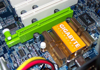
Moving back across from the SATA ports, we see VIA's VT8237 southbridge before reaching the aforementioned AGP 8x slot. The release mechanism for cards in this slot is a little different from that used by many boards, utilising a button which needs to be pulled out to release the card rather than the usual clip mechanism. Although it looks good in theory, in practice it turned out to be somewhat fiddly, especially with video cards with chunky heatsink arrangements.
Above the AGP slot, we find the passively cooled northbridge, featuring a pretty hefty heatsink. To the left of that is Realtek's RTL8110S chip which powers the board's Gigabit Ethernet capabilities.
Moving back down across the board's five PCI slots, we find to the left of the slots another Realtek chip, this time the ALC658 AC97 audio chip. This is followed by a couple of analogue CD connectors and the ITE-based I/O control chip. We then find ourselves at Gigabyte's now familiar Dual BIOS technology, where we can see both the main and backup BIOSes.
Along the bottom of the board we have the various connectors for the backplane gameport, S/PDIF, Firewire and USB ports, followed by all the usual LED connectors.
Moving back up, we find the IEEE 1394 control chip, which sides with the extra two IDE ports and finally the GigaRAID IT8212 chip which controls and offers the RAID functionality for these ports.
Gripes about the positioning of the SATA connectors and the AGP slot release mechanism aside, the layout of the board is very clean and simple, and leaving everything within easy reach.


