How we tested
Testing the PSUs consisted of first hooking them up to a HP/Agilent 6842A Harmonic Flicker Test System. While capable of a lot more than it was used for, I used the 6842A as little more than a glorified power supply. The US$16,000 6842A can be programmed to provide almost any output voltage at any frequency that you'd ever need, at least to test consumer electronics like PC power supplies. Programmed to feed a 230.00V constant voltage (usually an unmoving 229.9V or so on the 6842A's display when under load) at 50Hz (the U.K. mains supply frequency and voltage, basically), the 6842A was also my guide to input power, measuring the power draw created by the power supply being tested. It also showed me the PSU's PFC which is power factor correction, more on which later. Here's a shot of it in action.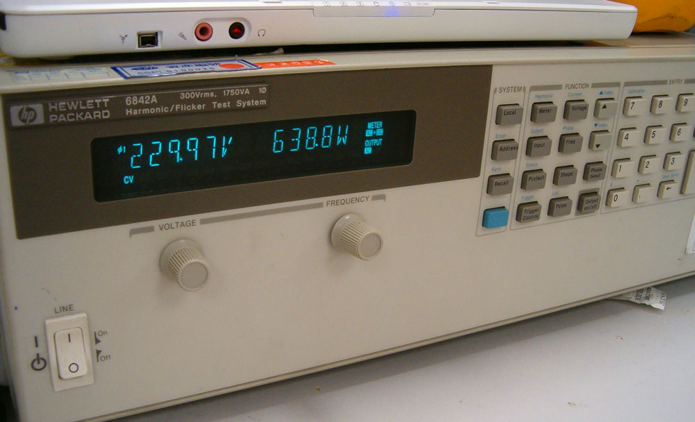
I need one of these for my testing. PD, David, are you listening?
Pictured above supplying a slightly crazy 638.8W of input power to a 480W power supply, so that supply could actually spit out its rated output power, the 6482A is the first link in the testing chain, giving a simulated mains supply to the units I wanted to test and a means to measure what the PSU was heaving in terms of power. After the 6482A fed the PSU, we then needed some apparatus to generate the load.
And a load generator, cheers!
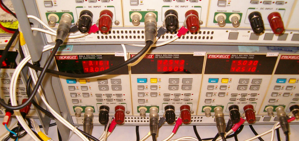
The load generator was an array of nine ProDigit 3311 300W modules in a ProDigit 3300A mainframe. The modules can generate up to 300W of load on their own, digitally regulated so we were able to step loads up and down in fixed amounts to make the resulting calculations easier, giving 2700W of possible load. Better to have too much ability than not enough, eh? In the photograph above you can see the in-progress testing of a supply, the picture capturing the +3.3V, one of the +12V and the +5V outputs. The top line of the display is the measured output voltage from the PSU, the bottom line is the current draw the module is pulling from the PSU.
It's alright, I can build this bit myself
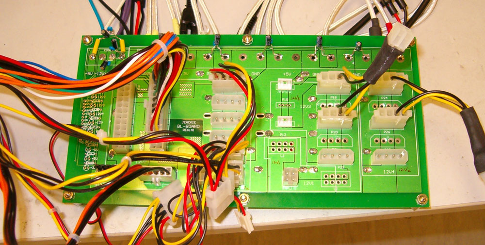
Connecting the ProDigit mainframe and module array to the power supplies was a custom built testing board. The custom board and associated adaptors let us plug in the connectors needed to load up any of the power supplies. We could plug in EATX 24-pin main connectors (and the 20-pin subset), 6-pin PCI Express connectors, lots of regular 4-pin Molex like you'd use for your hard or optical drives, 4-pin 'P4' connector (which is the left half of a 8-pin SSI connector, so we could test that one too) and the less common floppy and old 'half-AT' connector you still see on some supplies.
Testing procedure
With the correct equipment, testing the supplies was a fairly simple affair. Intel has a set of specifications for testing ATX and ATX v2.0 power supplies which are freely available on its website. Using those as a rough base guide, since they give you figures for loading up power supplies to a rated output power, we connected each supply in turn to the 6842A, custom board and ProDigit load generator using the correct cabling. Emphasis was always placed on maximising current draw from +12V for ATX 2.0 supplies wherever possible, to stress those independent rails. Otherwise we created output powers by staying within the stated limits of the supply, using some calculations to point us in the right direction.Power was then supplied to the PSU in an off state by the 6842A and the input power was recorded with a load equal to half that stated in the supply's literature as the maximum for +5vsb. +5vsb is the stand-by voltage the power supply gives out to trickle feed your PC when it's in stand-by mode, which is more or less the idle load for a PC when the system is off. So with the PSU off, a small load was applied to +5vsb to record idle power over a three minute period. The average was taken and that's what we report.
Then we attached the second probe from a Fluke 52 II digital thermometer to the section of the power supply where air would be exhausted by the PSU's fan(s). If the PSU was fanless, we attached the probe to where an exhaust fan would reasonably be, on the back edge where the power cord is connected. The first probe on the Fluke was taped to the test bench, poking out into the lab, away from the PSU testing area. That recorded ambient temperatures throughout testing. So before load testing began, we recorded ambient and PSU temperatures.
Load testing then began by setting the ProDigit hardware to extract a current draw from the rails on the PSU which would result in an output power of around half what the PSU was supposedly capable of. After checking that was a stable load for the PSU to handle over a 5 minute period, we recorded ambient and PSU temperature again before starting to increase PSU load towards its rated maximum.
Loads on the connected rails were increased towards the maximum required values needed for the stated output power to be drawn. After increasing the loads on the rails, the values were input into our collecting spreadsheet and temperatures recorded again. If the PSU appeared to be handling the load step correctly, it was allowed to provide the load for 90 seconds before load was increased again and everything recorded. One step of load was around three minutes in duration, comprised of 90 seconds of data collection and the observed 90 second load period.
That step was repeated until the PSU was either unable to complete the intermediate load condition test, or it was set to value that corresponded to the output power it advertised itself as having. When the power supply was generating the required output power, a double check of the figures was performed to make sure everything was correct and then a 30 minute load test period was performed. Every thirty seconds temperatures were recorded and the rail voltage levels were observed, recorded and fed into the spreadsheet to make sure output power was being maintained.
So over a thirty minute load test at the required output power, 60 full sets of readings were taken to make sure the power supply was performing in terms of output power, temperature, input power (and therefore efficiency, more on which later) and voltage fluctuation.
If the power supply made it to the end of the thirty minute period, a pass was declared; otherwise the time into the test that it failed was recorded. The PSU was then switched off, the values for the ProDigit array were reset to sane levels and the 6842A's output supply was switched off to give it a quick breather while we set the equipment up to test the next unit.
I've mentioned input and output power more than a few times already, and to many it won't be immediately clear why there's two power figures to report. Time to explain how we calculated everything.