Volt Modding Fans
The principle behind this mod is to drop the voltage supply to the fans, slowing the fan speed and therefore reducing the noise created by the fan. There are three main methods of doing this:- 7 volt modding the fan
- Baybus
- Rheobus
This is so easy its unreal, the principle behind it , is that the normal supplied voltage for a case fan is 12 volts.
If you can lower this voltage you can reduce the fan's noise.
The problem with this is that computer PSU molex supplies either 12 volts or 5 volts.
5 volts being a bit too low to provide any decent air movement from the fan.
How to get around this is to instead of using the 12v line and the 0v line to provide 12 volts, but use the 12v line and the 5v line to produce (12-5)=7v
Use the picture below to see how the fan is re-wired.

Note sometimes the black fan wire can be blue in colour.
The problem with the 7volt mod trick is that once the fan is set at 7volts there is no quick way of reversing this.
If you wish extra cooling (when playing games for example). The baybus was introduced to get around this.
It gives you the ability to switch between 7v , 12v and off. A full guide can be found here

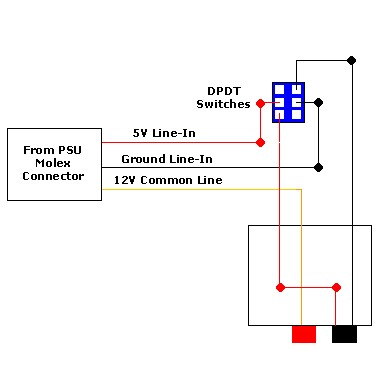
Now for the purpose of this project I wanted a much more simplified circuit
than normally found on baybus circuits. I am not going to have the switches
in a spare bay plate with two led's per switch, but I am going to put
the switch in a spare pci blanking plate at the rear of the case. Below
is the circuit design that I used. The switches can be found at Maplins,
part number FH05F
The circuit is very easy to create , it takes 15mins to create. The finished
circuit was mounted in the same pci blanking plate as the switchbus discussed
later. If you don't wish to make it yourself , there are many part built
kits on the market or a more personal service can be found at Baybus.co.uk
A rheobus is the next step in fan control. A rheobus gives you the ability to run your fans at any voltage between 12 and 0 volts.
This is slightly more complicated to create yourself. The most basic design for a rheobus circuit is shown below.
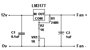
A full guide on the building of a rheobus circuit can be found here.
The circuit is fairly simple to build. Those with previous experience of soldering and circuit building should have no problems.

The picture above shows a rheobus in action. This is one that I had in one of my old cases.