VIA Epia MII motherboard
From a brief look at the Epia MII motherboard, you can easily see
just how packed out the small design is. Despite this, everything
is well laid out and easily accessible, making installation of the
motherboard, RAM etc far easier than the potential nightmare plugging
items into such a small board could potentially have been.
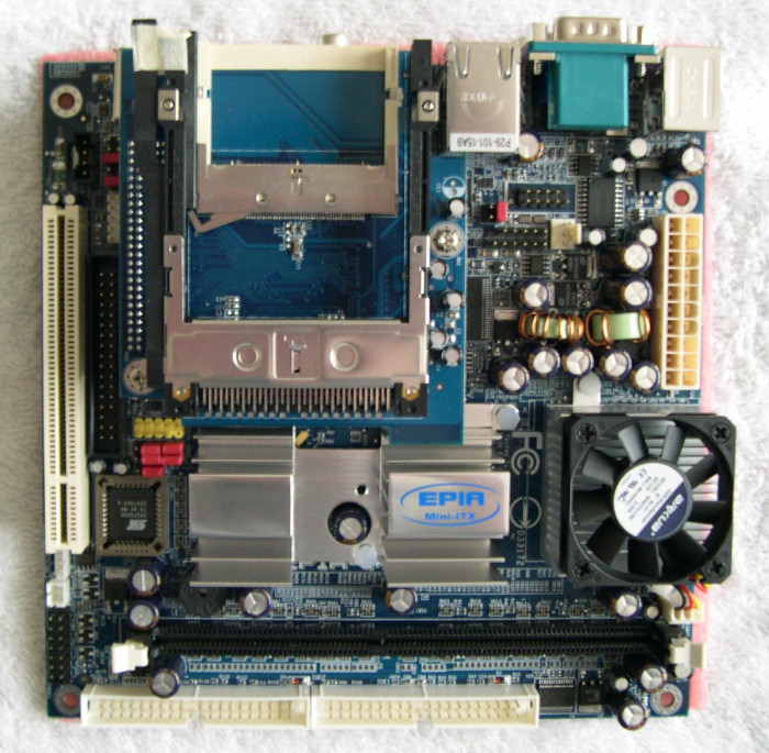
Looking at the motherboard from the bottom, we first come across its two ATA channels, above which is situated the single RAM slot for the board. Next up, on the right hand side, we find the VIA C3 processor, housed under a smallish heatsink and fan. Alongside this are the boards north and south bridge, both covered by heatsinks.
Across the left-hand side of the board we see the space into which a riser card can be plugged, allowing additional an additional PCI device to be attached to the board. Next to this are headers to attach additional or case-mounted USB and Firewire ports to. We then find the add-in module containing one PCMCIA and one CompactFlash slot. On the very left-hand edge of the board is the 20-pin ATX connector.
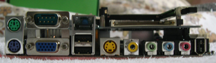
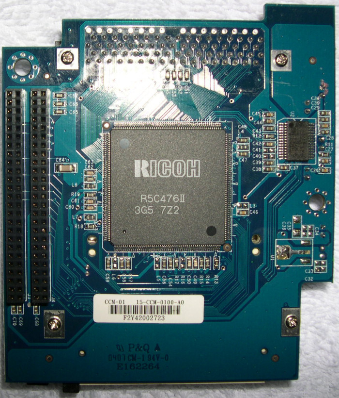
Looking at the connectors on the back of the motherboard now, from left to right, first we find the board's two PS/2 connectors, followed by a single 9-pin serial and 15-pin VGA connector. We then have the 10/100Mbps LAN port, along with two USB ports. Along the bottom of the back plane, we then have S-Video, SPDIF, line-out, line-in and microphone connectors, before a solitary FireWire port. Above that we see the aforementioned PCMICA and CompactFlash slots. On the underside of the expansion module containing these PCMCIA and CF connectors, we can see the Ricoh chip controlling this functionality.
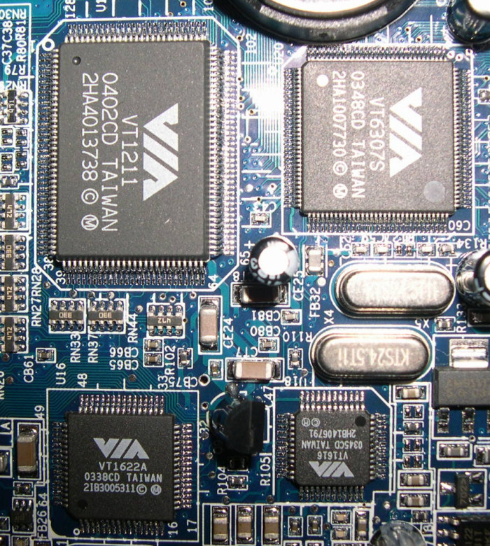
On the motherboard itself underneath this expansion card, we find a plethora of VIA chips hidden away - A VT1211 chip for hardware monitoring, VT6307S to give the board its FireWire functionality, VT1622A for hardware TV encoding to support the boards TV-out capabilities, and last (but not least) VT1616 to deal with the Epia's audio output.
Certainly a small but perfectly formed motherboard on show here. But what to put it in? Let's now take a quick look at an example of a Mini-ITX case in which to house your Epia.