


Internal Appearance
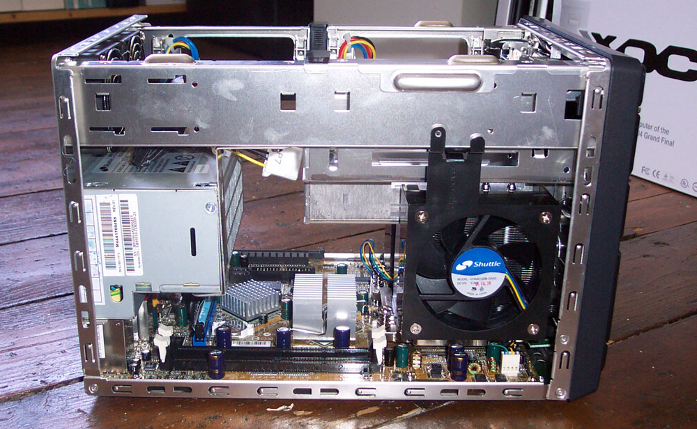
If you remove the chassis cover after removing the four thumb screws and have a look at the left side, you'll see the exhaust fan for the CPU cooler on the left, which you can hinge out once you've removed the cooler, to get better access to the CPU socket. The DDR2 memory slots aren't far away, in the gap that the PSU makes with the exhaust fan, on that edge of the mainboard. There's room, height-wise, for tall memory modules. Laterally there's not too much room, though, so be careful if the heatspreaders on your memory modules are on the fat side.

A peek round the other side shows the shroud that's enclosed by the panel duct on the chassis, the PCI Express slots and another look at the passive coolers for the i925XE bridge and the ICH6R.
The cabling for the drive bays at the top of the chassis, which I'll show you soon, can been seen in the photograph above. Clipped to the side of the PSU after they're connected to the mainboard, Shuttle run the cabling up the interior of the front of the chassis before pulling it along the top spar, clipping it out of the way until you need to use it. There's SATA power and data cabling run to both bays, showing the SB95P's obvious SATA bent.
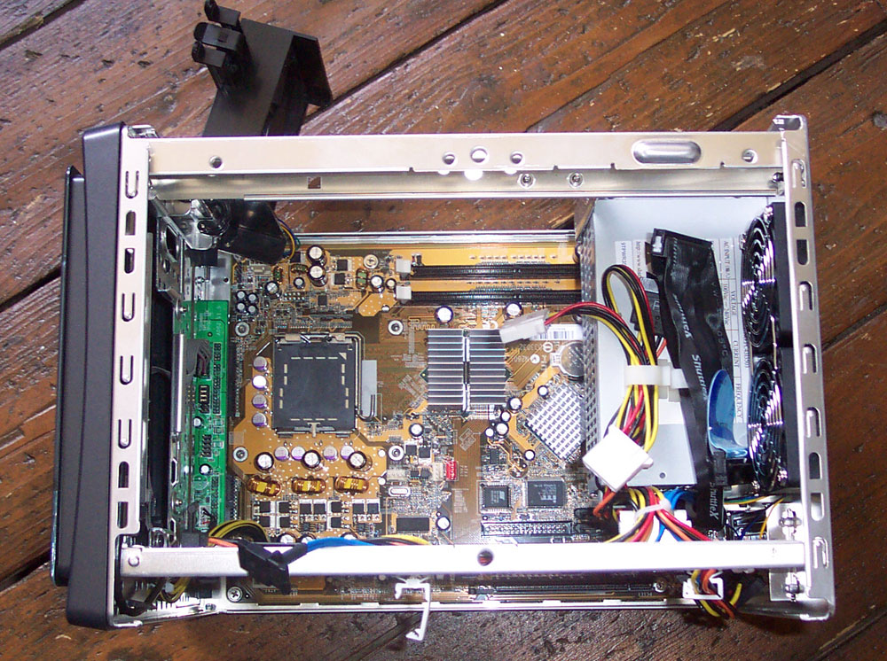
Having a look near the PSU area shows you how Shuttle organise the internal cabling in that part of the interior.
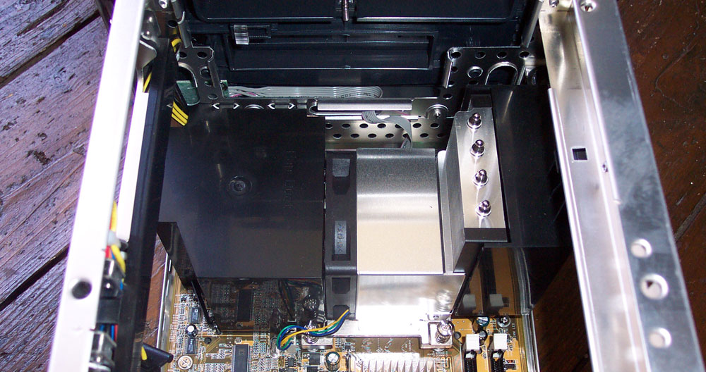
Removing the cooler, as I've done in the picture above, lets you remove the shroud I showed you above and hinge out the exhaust fan. The cooler doesn't arrive with a protective plastic strip on the bottom, so it looked like this when the XPC arrived from Taiwan. If yours arrives in the same way, bust out the heatsink cleaner and give it a good seeing to.
Removing the cooler is a simple matter of finding a long barreled Philips screwdriver and unscrewing the cooler at four corners, before lifting it out vertically from the cooler area.

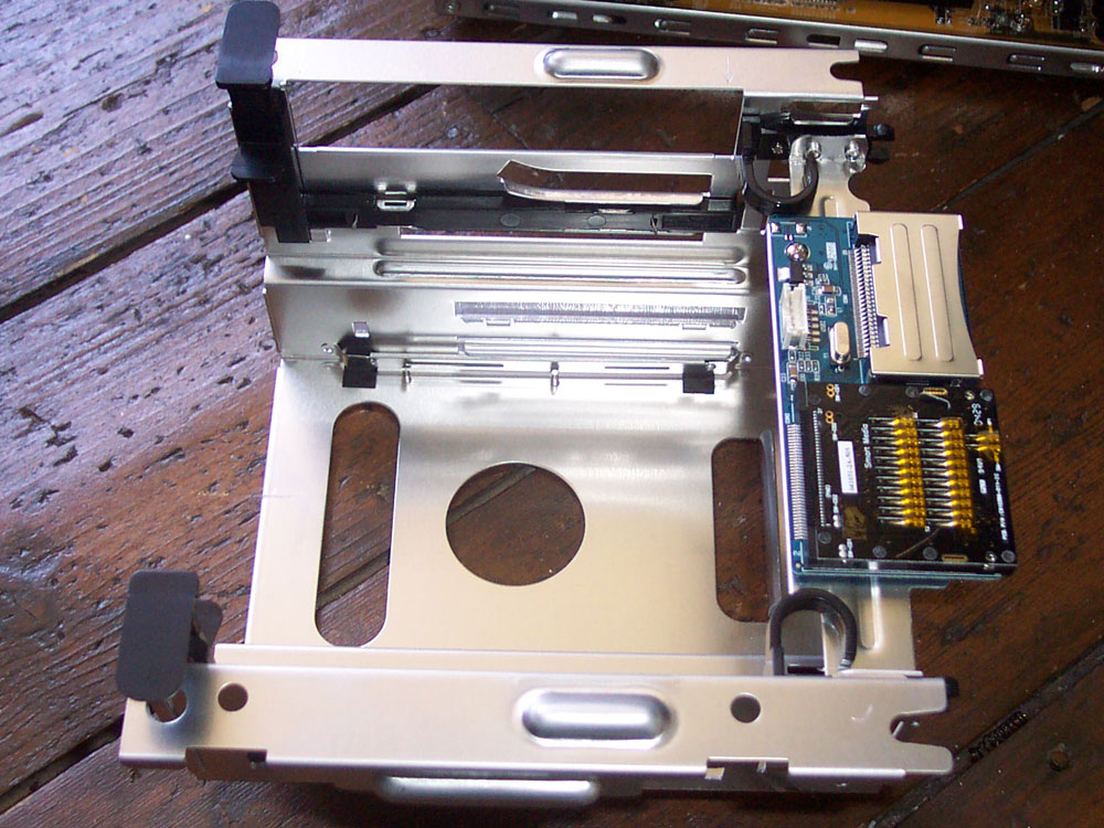
The photograph above shows you the brackets attached to the hard drive and the method you use to install them. Attach the rails, hook the hooked ends over a bar on the top spar, then lower the drive down into the space and secure it with the hinged latch. Tool-free operation from start to finish means disk drives are simple to install or swap. The drive's data and power connectors are then exposed through a gap in the top spar, allowing you to attach the prerouted cabling I showed you earlier.
Here's the SB95P v2.0 with a single hard disk and optical drive installed, so you can see how everything fits together (the optical drive and third hard disk or floppy drive reside in the removable drive cage).

Installing the optical drive is very similar to installing a hard disk. You attach the correct rails to the drive and slide it into the drive cage. A latch on each rail secures the drive and the cage it sits in to the rest of the chassis.


